Lab 4 - Reverse Engineering and Logic Locking
2026-01-12 | Hackster , Labs , Reverse Engineering , Logic Locking
Introduction
This lab goes through simple logic locking on a combinatorial circuit design, and the implementation of a SAT attack to determine the key used for logic locking. The SAT attack can be performed using a comparison of netlists for the locked and unlocked device. You may also implement the SAT attack using MicroPython, or just use simple brute force (given that the cores are relatively small).
Goals:
- Correctly interpret the behaviour of a provided combinational logic circuit using a provided binary with no logic locking
- Analyse the provided netlist to carry out a SAT attack and determine the key used for the hardware design using propositional logic solvers
- Automatically determine the correct key for the locked circuits using the locked binary and behavioural description (i.e. truth table) of the unlocked binary
Getting Started
- Download
lab4_bitstreams.zipfrom Moodle and unzip the contents intohackster-programmer/diy, this includes the required Makefile,run_circuit.py,circuit_prop.txt, binaries, and.jsonnetlists for the locked and unlocked circuits.
The python script, run_circuit.py, currently will set all the inputs to 0, and reflect the output values on the two RP2040 LEDs (APP1, APP2)
The netlists and binaries will be prefixed with your zID (zXXXXXXX_locked.bin, zXXXXXXX_unlocked.bin, zXXXXXXX_locked.json).
To load the unlocked binary onto the hackster, replacing the zID with your zID, use:
ZID=zXXXXXXX make run_fpga
To load the locked binary onto the hackster, use:
ZID=zXXXXXXX make run_fpga_locked
Interpreting hardware behaviour
With the unlocked binary loaded onto the hackster, and starting with run_circuit.py, write a program to check the behaviour of the circuit.
At this point, the circuit should be the unlocked version, so the key doesn’t need to be set. Using this, fill out the truth table in circuit.csv.
| I/O pin schematic label | Direction | Value |
|---|---|---|
| APP_ICE40_D0 | Input | input[0] |
| APP_ICE40_D1 | Input | input[1] |
| APP_ICE40_D2 | Input | input[2] |
| APP_ICE40_D3 | Input | input[3] |
| APP_ICE40_D4 | Input | key[0] |
| APP_ICE40_D5 | Input | key[1] |
| APP_ICE40_D6 | Input | key[2] |
| APP_ICE40_D7 | Output | output[0] |
| APP_ICE40_D8 | Output | output[1] |
The provided circuit uses all the available digital I/O pins, these can be read/written to in the micropython script. Typically, the key values would instead be stored or accessed separately, however for this exercise, inputs and key values are all provided via the same RP2040 AppMicro GPIO.
SAT attack and translating the netlist
From the provided .json file, determine the behaviour of the locked circuit using gate definitions, and convert these into propositional logic statement(s), using the syntax for the SAT solver on logictools.org.
This could be done as a single statement for both output values, or be separated for each output.
Use the method in High-Level Approaches to Hardware Security (section 4) to determine the key.
For the locked circuit, this module is named “circuit_locked”, for the unlocked circuit, the module is named “circuit”. In the provided files, in the module, bits 3, 4, 5, 6 should correspond to the inputs 0, 1, 2, 3 respectively.
"ports": {
  "ICE_CLK": {
    "direction": "input",
    "bits": [ 2 ]
  },
  "APP_in": {
    "direction": "input",
    "bits": [ 3, 4, 5, 6 ]
  },
  "APP_key": {
    "direction": "input",
    "bits": [ 7, 8, 9 ]
  },
  "APP_out": {
    "direction": "output",
    "bits": [ 10, 11 ]
  }
}
The json netlist generated by Yosys defines the circuit with multiple LUT4s, below is an example LUT4 definition for an and gate (inside the “cells” for the module) - both I1 and I0 are unused, so in the truth table only states with I1 = I0 = “0” will occur.
LUT_INIT defines the output values for each of the input combinations from [15:0]. More documentation about the json netlist generated by yosys can be found here, the full explanation of SB_LUT4 primitive is here (see Page 47-48).
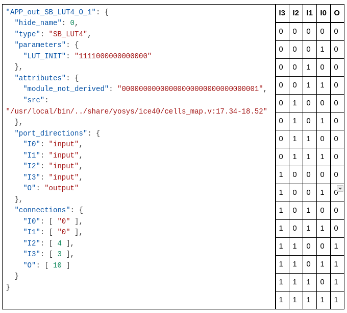
LUT4 example
Challenge Task: Programmatically determine the key bits
Write a Python script, get_key.py, which is runnable on the RP2040, to determine the correct key using the expected behaviour of the unlocked circuit and the provided locked circuit (zXXXXXXX_locked.bin). In this case the design is quite small so can be determined by brute force (worth 1 mark) or by using a programmatic SAT attack (2 marks).
Resources
Resources:
- High-Level Approaches to Hardware Security
- https://doi.org/10.1145/3577200 or also available at https://arxiv.org/pdf/2207.10466
- Specifically section 4 covers logic locking and IP protection
- SAT Solver - https://logictools.org/prop.html
- Netlist Syntax
- https://yosyshq.readthedocs.io/projects/yosys/en/latest/cmd/write_json.html
- Syntax of the netlists generated by Yosys
- https://www.latticesemi.com/~/media/latticesemi/documents/technicalbriefs/sbticetechnologylibrary201701.pdf
- Documentation of ICE primitives including SB_LUT4 on page 47-48.
- https://docs.amd.com/r/en-US/ug953-vivado-7series-libraries/LUT4
- Documentation of LUT4 initialisation, this is not specific to how Yosys synthesises the circuits but is helpful in understanding the LUT4 behaviour.
- https://yosyshq.readthedocs.io/projects/yosys/en/latest/cmd/write_json.html
Video resources:
- Logic Tools Part 1 - Introduction to propositional logic and the logictools SAT solver.
- Logic Tools Part 2 - Walkthrough of the SAT attack on the provided locked circuit, using the netlist and propositional logic statements.
Deliverables and Weightings:
This lab is worth 10% of your final grade for this course.
Deliverables:
- A single zip file containing the following:
circuit.csv- Documentation of unlocked behaviour and the determined key values
- Submit filled in version of the provided circuit.csv with outputs of unlocked binary for each valid input
[zID]_unlocked.bin,[zID]_locked.bin- These are the bitstreams we provided to you. Provide them back.
run_circuit.py- Micropython used to check all output values from the unlocked circuit
- Starter code has been provided in
lab4_bitstreams.zip
circuit_prop.txt- a text file containing the propositional logic representation of the circuit and truth table expressions for the locked circuit, and the propositional logic expression(s) to determine key values, and truth table expressions for the netlist of the locked circuit
- A template circuit_prop.txt has been provided to be filled in
get_key.py- A MicroPython script runnable on the RP2040 AppMicro to determine the key, based on the behaviour of the unlocked circuit
Grading Rubric
SAT Attack on Logic Locking (10%)
- Criterion:
- (2%) Determining unlocked behaviour and filling out truth table
- Fail (0%) No attempt, or incoherent/mostly incorrect table.
- Genuine Attempt (1%) Truth table contains multiple errors, run_circuit.py close to getting correct outputs, but not quite correct.
- Mostly Correct (1.5%) Truth table is mostly correct, with errors that could be explained by a single incorrect input.
- Correct (2%) Completely correct truth table for the provided circuit. Python script run_circuit.py which checks all these values.
- (6%) Derives a correct propositional formula for the locked circuit and uses the SAT solver to determine key values.
- Fail (0%) No attempt, or completely incoherent propositional logic statements and/or key value determination.
- Genuine Attempt (1.5%) Makes partial progress in deriving propositional formulas or writing SAT solver inputs.
- Partial Success (3-4.5%) Propositional formula(s) provided, and SAT attack completed, determining at least one correct key bit. With minor changes could determine other key bits.
- Correct (6%) Propositional formula(s) provided for the behaviour of the locked circuit correctly. Fully carries out SAT attack with correct, key values written in circuit.csv.
- (2%) Challenge Task: Programmatically determine locked circuit key values.
- Fail (0%) No attempt, or completely incoherent program/script.
- Brute Force (1%) A micropython program which brute forces the key values, by checking all possible combinations of key values and comparing the output to the expected behaviour of the unlocked circuit.
- SAT Attack (2%) A micropython program which implements all steps of a SAT attack to determine the key values automatically.
- (2%) Determining unlocked behaviour and filling out truth table